One of the most widely used types of wire and cable for motorcycle electrical system is its low voltage type. Low voltage (LV) cables refer to copper-aluminum cables insulated with various polymers for voltages of 300 to 3000 volts.
In terms of conductor type, these types of cables include fixed cables, single-cable cables, sprayed cables, round semiconductor cables, sectored semiconductor cables, and compressed semiconductor cables.
A wide range of these low voltage cables are also available in flame retardant, reinforced, halogen free, hydrocarbon and oil resistant cables. These cables are designed for the work environment in which they are used.
Generally, these cables are used in places where the electric flux is at the cable standard or mechanical shock is low, while the armored type is usually used in places where there is a possibility of mechanical damage.
Low pressure cables have very wide applications, for example, they can be used in electrical installations, lighting, residential and commercial buildings, transmission of driving power of electric motors, etc.
This type of cable can be buried in the ground or installed in a channel. In fact, another use of low voltage cables is wiring for low consumption electrical appliances. Finally, it should be said that depending on the type of cable produced, different applications can be mentioned; In fact, any cable that is chosen must be completely compatible with the environment in terms of construction and performance.
Each cable is made of a different sheath and assigned a different symbol. And in general, low voltage cables have different structures and are used in different places, for example, NYY cables have a copper conductor and its cover is plastic.
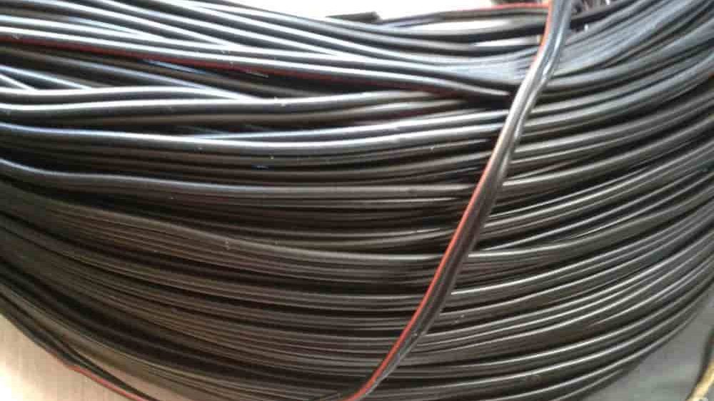
NKBA cables have copper conductors with paper sheaths, sheaths made of lead, steel, gold, and sheaths made of vegetable fibers. When choosing the type of cable, you should specify its type and use it in the right conditions.
The conductors are high voltage or HV aluminum or copper cables insulated with XLPE and are usually used for voltages above 36 kW.
Now let’s look at the difference between low voltage and high voltage cables:
The main difference between these two cable models is their different structure. Basically, in the high-voltage or high-voltage cable, if these layers are not present in the structure of the low-voltage cable, two internal and external semiconductor layers are seen.
The next difference between these cables is their type of insulation. In general, the insulation in low pressure cables is polymer type, while polyethylene cross-link is used for high pressure cables. Basically, due to the use of this insulation, several semiconductor layers are observed, which in the construction of high voltage cables isolate the electric field inside the cable, and external currents will not be able to affect the internal electric field.
Another difference between these cables is their thickness. Their thickness will be different depending on the type of insulation used. In general, high voltage cables are thicker than low voltage cables and end up being heavier.
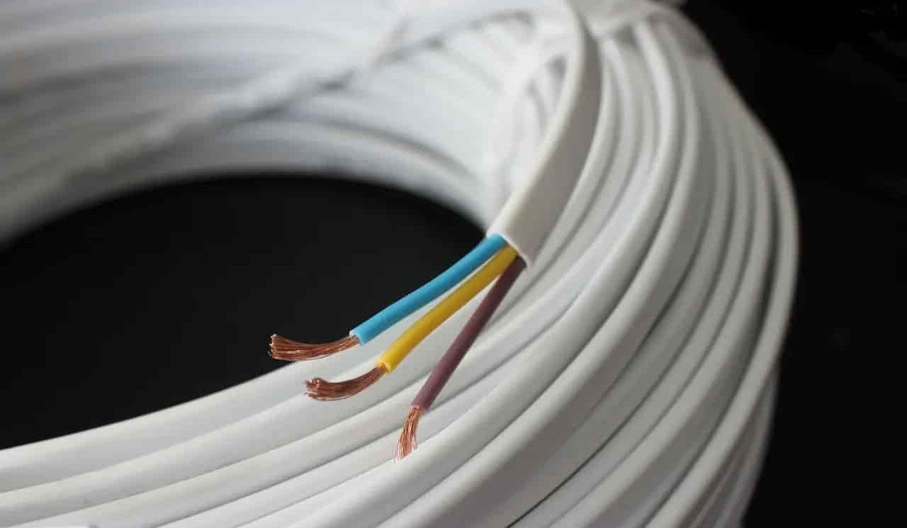
Low voltage cable for motorcycle
Low voltage wires and cables are used to transmit electricity to various components of the motorcycle. When it comes to the power of your motor, the words “watts”, “volts” and “ohms” can really confuse you. To solve the electrical problems of the engine, you must be familiar with the basic and important physical terms and principles of electrical systems.
Here we will explain the basics of electric motor systems and address common concerns about working on motorcycle electrical systems. Current flow in a motorcycle DC system is the migration of negatively charged electrons from the negative terminal of a power source (such as a battery) to the positive terminal through cables and consumers (such as a light bulb).
With alternating current, the current direction is constantly changing. For example, the unrectified current from the generator flows to the motor voltage regulator/rectifier unit, where it is rectified and then fed into the DC electrical system. This can be explained by comparing amperes and the effect of conductors to the flow of water in a pipe.
The water pressure at the end of the pipe depends on its diameter, the larger the water source and the larger the diameter of the pipe, the higher the water pressure.
For electricity, the cross-section of the connected power cable corresponds to the diameter of the pipe. The thicker and shorter the cable, the more efficiently it conducts current, so the current encounters less “resistance”. The longer and thinner the cable, the greater its “resistance”. It depends on the material, section, length and temperature.
Resistance is measured in ohms (Ω) and the formula symbol R is used. This cable is made of metal and does not conduct current very smoothly. If the cable is too thin or corroded, it can get very hot and even burn the insulation (the cable catches fire). Use electrical fuses to prevent this type of damage.
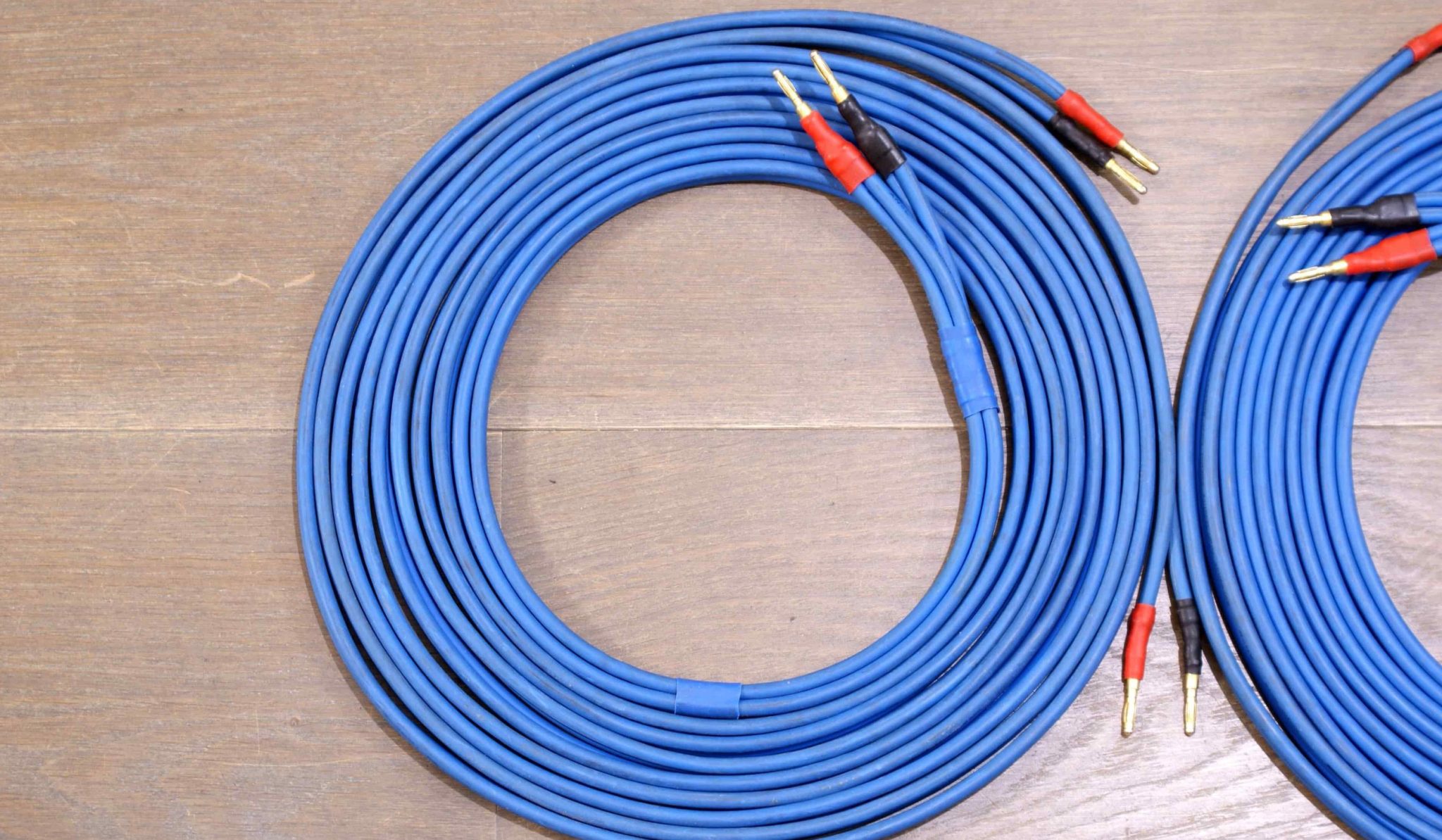
They act as predetermined break points on mechanical components, such as opening the circuit in the event of a short circuit. As a result, they prevent damage to batteries and electrical components, as well as cable fires.
In addition to ensuring that the cable is of sufficient thickness for the respective application, contacts such as clamps and connectors must be free of corrosion and dirt to keep the contact resistance as low as possible.
As far as possible, avoid using terminal blocks and branches on the motor. Because they increase the cable resistance for no reason and do not create a safe and vibration-resistant connection. The negative/ground wire must be the same quality as the positive wire.
Voltage is the potential difference between the negative and positive terminals. The battery is charged by a charger or dynamo, which is called the “alternator” of the engine. It produces a voltage through the rotating motion of an electric coil in a magnetic field.
Another important factor in the circuit are amplifiers. It is measured in amperes (A) and has the formula symbol I. The ampere states how many electrons flow through the cross section/resistance of a conductor (power line) in a given time.
In a circuit, current flows only when that circuit is also closed. A circuit basically consists of a voltage source, cables and one or more consumers. The single conductor system is commonly used in motorcycles, ie.
The cable connects the positive terminal of the battery to the corresponding consumer (eg lamp) through a switch (eg ignition).
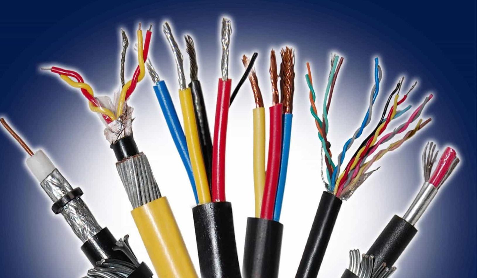
The return path is provided by the jumper wire and the metal frame of the motorcycle, called the ground wire, which is connected to the negative terminal of the battery. If the ignition is turned off, the battery is disconnected from the electric circuit to the electric motor and the electric motor does not work.
Motorcycle electricity is divided into several circuits. Motorcycles are not approved for road use if they do not have the following circuits:
The circuit charges the battery through the alternator and voltage regulator/rectifier.
The ignition circuit supplies power to the ignition unit, ignition coil and spark plug.
The lighting circuit powers the headlights, instruments, and taillights.
There are other smaller independent circuits. Brake lights are activated by front and rear brake light switches, turn signals, lights, horns, and sometimes hazard lights.
Modern motorcycles are equipped with a large number of additional circuits, such as engine water cooling to control the thermostat and its fan, as well as computer-aided injection electronics with various sensors or brake assist (ABS).
In order to reduce the wiring costs of the electrical system of the engine computer and also to facilitate the connection of additional components, the use of the technology known as CAN-bus to connect electronic components through short holes is becoming more and more common. Data lines.
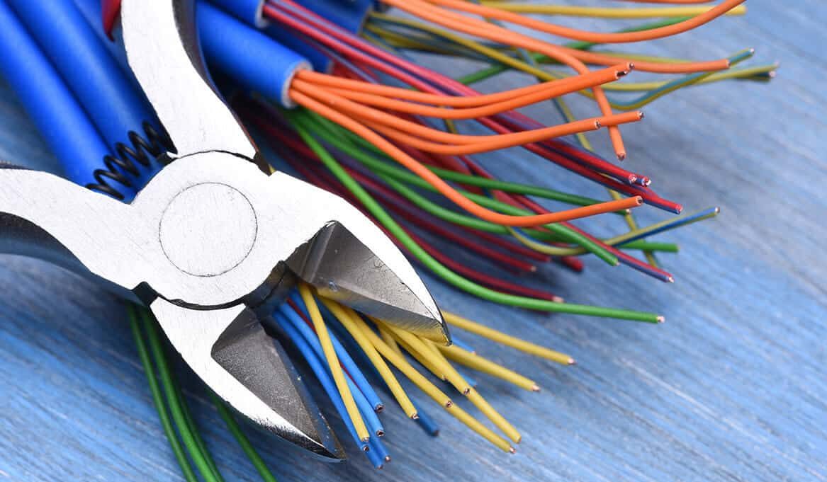
Low voltage wire for motorcycle
As mentioned, in the electrical system of a motorcycle, low voltage cables and wires are generally used to supply power to some parts such as the head lights and brake lights.
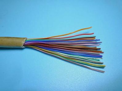
In fact, different wires in different motorcycle models have different functions, which are indicated by their wire colors. Therefore, among the normal blue, green and gray wires, it is not possible to directly determine which one is the brake light wiring. However, of the three wires, the green wire is more likely to be the ground wire.
To determine which is the brake cable, look at the front brake switch or rear brake switch wires. If there is a blue line, the blue line is the brake. The light wire, if there is a gray wire, the gray wire is the brake light wire. Or by looking at the headlight wires, you can tell which one is the light wire and the other is the brake light wire.
Motorcycles on the market generally have three wires, and the black wire is generally the common wire, which is the negative pole of the power supply. There are also two wires, one is the drive wire and the other is the brake wire, which is the positive pole of the power supply.
We can connect the battery first, define the line definition, and then connect the car, but in this process, pay attention to the insulation of the end of the line.
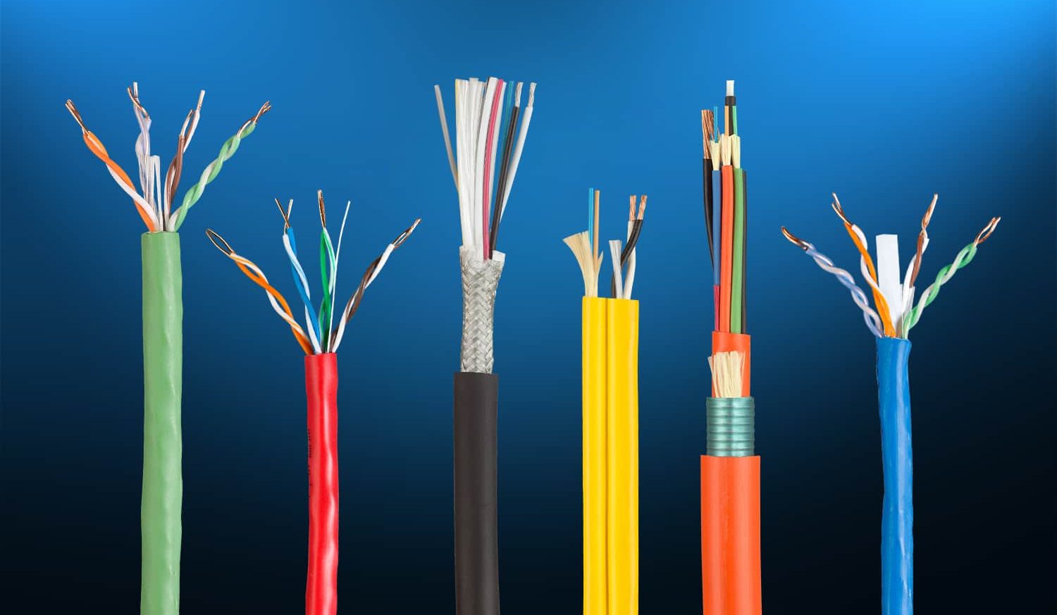
Since there are many lines on a motorcycle? In fact, not only that. Removing steering cables on motorcycles is complicated. Take Honda motorcycles as an example. The red and black lines belong to the positive pole of the car.
The green line belongs to the negative pole of the whole vehicle. Blue and white lines are hair strengthening lines. The black and white line is the flaming line. The yellow line is the rectifier line and the red and black lines are the magnetic high voltage lines. The orange wire is the magneto or low voltage wire. The bright green wire is the horn wire, and the color of the Daewoo Honda gas wire is also different.
Are the positive and negative poles of the motorcycle control line also related to its color?
It is true because generally red is positive and black is negative (that is, the lines we usually call them), the red and black lines are the low voltage coil for the ignition or charging the battery (there are also yellow or white wires. of the wire The low voltage screw is charged to the battery, and the batteries or signal lights come directly to the rectifier. The high voltage closed wires are generally black and white, the light blue and yellow lines are usually turn signal lines, the headlights are Red lines.
white) and gray is a small light. Note that all super negative (black wire) devices have been removed or are directly connected to the car’s conductor rail.
Your comment submitted.